Casa / Prodotto / Cuscinetto lubrificante in solido JDB / JGBF Brass Oilless Ejector Flanged Guide Bearings Bushings
all ingrosso JGBF Brass Oilless Ejector Flanged Guide Bearings Bushings

JGBF Brass Oilless Ejector Flanged Guide Bearings Bushings

Descrizione del prodotto:

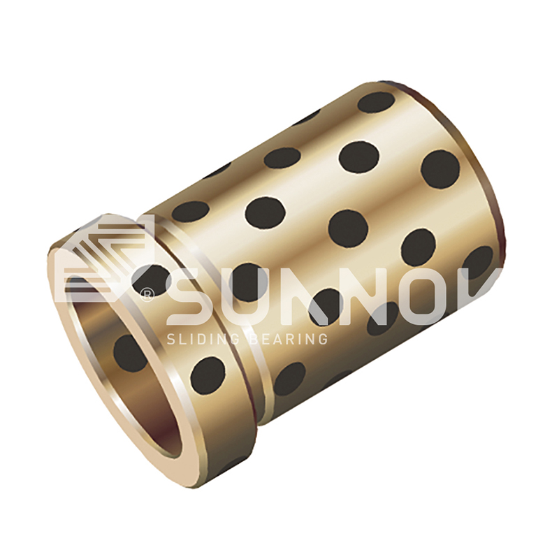
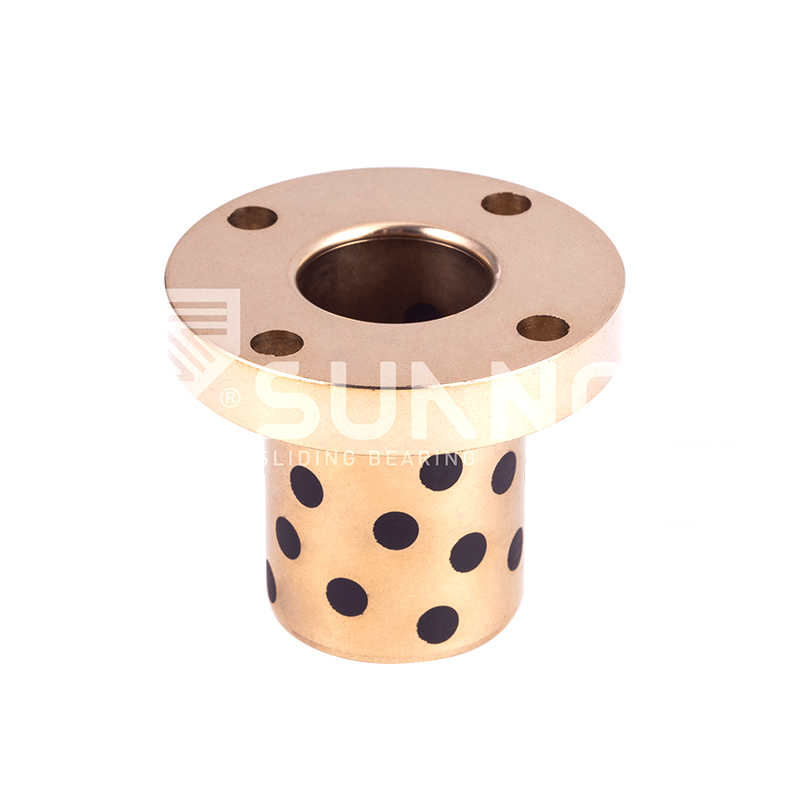
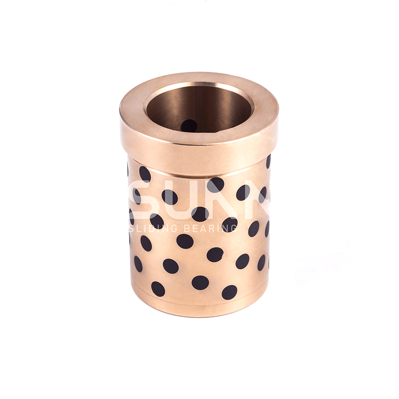
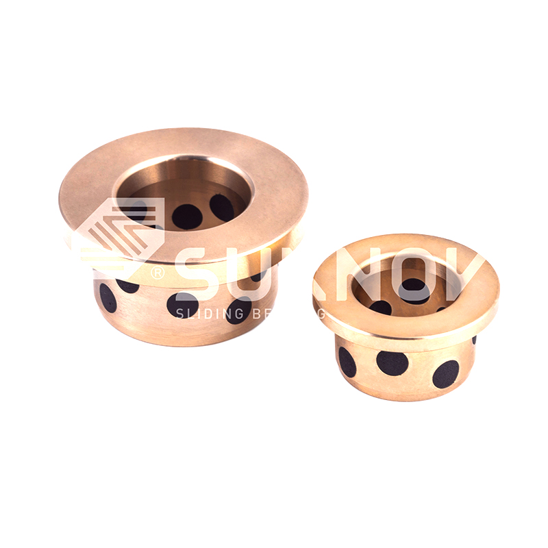
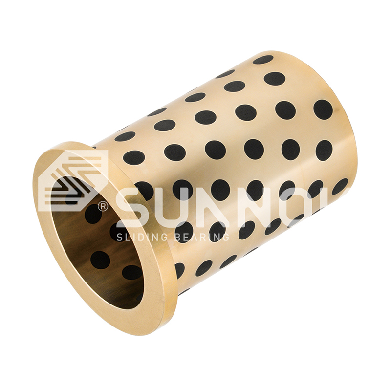
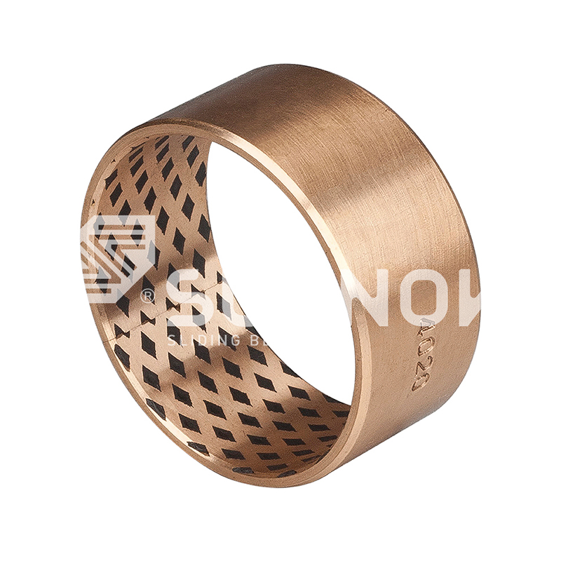
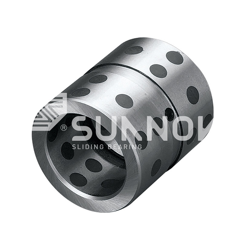
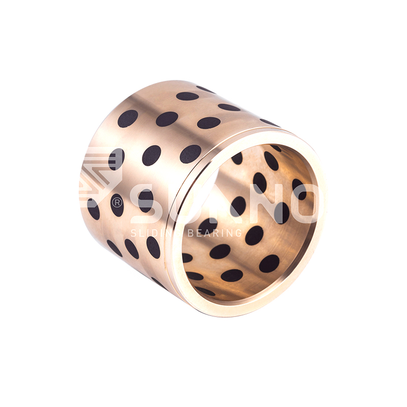
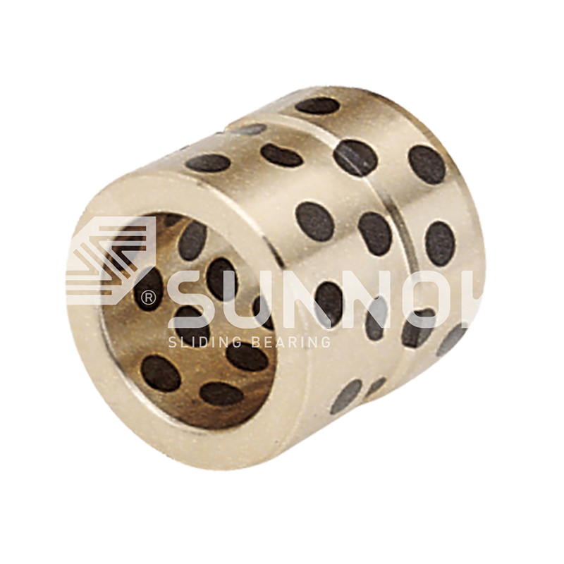
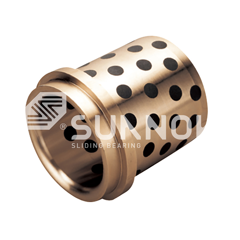
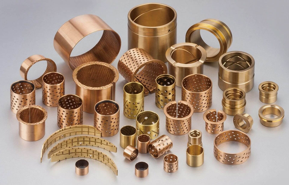
JGBF Brass Oilless Ejector Flanged Guide Bearings Bushings Brass is used as the base material and graphite solid lubricant is embedded in it, which has self-lubricating properties. The bearings have a low friction coefficient (0.05-0.12) and can operate stably under high load and high temperature environments without external lubrication. They have strong wear resistance and long service life. JGBF bearings are corrosion-resistant and suitable for a variety of harsh working conditions. Applications include machinery manufacturing, automobiles, construction, port machinery, agriculture, medical treatment and wind energy, and are widely used in equipment that requires high precision, high load capacity and maintenance-free operation. There are a variety of standard sizes to adapt to a variety of mechanical equipment.

Descrizione del prodotto

Standard No. d L d  G6 D  m6 D1 T L1
JGBF-12×19 12  19  12  +0.016
+0.006
18  +0.018
+0.007
25  19 
JGBF-12×24 24
29
24 
JGBF-12×29 29 
JGBF-12×34 34  34 
JGBF-16×19 16  19  16  25  +0.025
+0.009
30  19 
JGBF-16×24 24  24 
JGBF-16×29 29  29 
JGBF-16×34 34  30 
JGBF-16×39 39
49
30 
JGBF-16×49 30 
JGBF-20×24 20  24  20  +0.020
+0.007
30  35  24 
JGBF-20×29 29  29 
JGBF-20×34 34  34 
JGBF-20×39 39  39 
JGBF-20×49 49 40 
JGBF-20×59 59 40 
JGBF-25×24 25  24 25  35  +0.025
+0.009
40  24 
JGBF-25×29 29 29 
JGBF-25X34 34 34 
JGBF-25X39 39  39 
JGBF-25×49 49  49 
JGBF-25×59 59 50 
JGBF-25×69 69 50 
JGBF-30×29 30  29 30  42 47  10  29 
JGBF-30×34 34 34 
JGBF-30×39 39  39 
JGBF-30×49 49  49 
JGBF-30×59 59  59 
JGBF-30×69 69  60 
JGBF-30×79 79  60 
JGBF-35×39 35  39  35


+0.025
+0.009
48 +0.025
+0.009
54  10 39 
JGBF-35×49 49  49 
JGBF-35×59 59  59 
JGBF-35×69 69  69 
JGBF-35×79 79  70 
JGBF-35×89 89  70 
JGBF-35×99 99  70 
JGBF-40×39 40 39  40 55 +0.030
+0.011
61 39 
JGBF-40×49 49  49 
JGBF-40×59 59  59 
JGBF-40×69 69  69 
JGBF-40×79 79  79 
JGBF-40×89 89  80 
JGBF-40×99 99  80 
JGBF-40×109 109  80 
JGBF-50×49 50 49  50 70 76 12 49 
JGBF-50×59 59  59 
JGBF-50×69 69  69 
JGBF-50×79 79  79 
JGBF-50×89 89  89 
JGBF-50×99 99  90 
JGBF-50×109 109  90 
JGBF-50×119 119  90 
JGBF-60×99 60 99  60  +0.029
+0.010
80  86  15  99 
JGBF-60×109 109  109 
JGBF-60×119 119 110 
JGBF-60×129 129  110 
JGBF-60×149 149  110 

Introduzione al prodotto

Flanged Ejector Guide Series

JGBF Brass Oilless Ejector Flanged Guide Bearings Bushings

300
°C
Operating Temperature
Flanged
Configuration
Integral Retention
0.18
μ
Friction at 250°C
Flanged Guide Architecture

The JGBF series combines high temperature brass substrate with an integral flange designed specifically for ejector guide applications. The flange provides positive axial location within the mold or die platen, eliminating the need for separate retaining rings or shoulder bolts. This configuration simplifies installation and ensures consistent guide positioning during thermal cycling. Graphite lubricant inserts are distributed across both the cylindrical guide bore and the flange thrust face, providing lubrication for both radial guidance and axial seating contact. The flanged design also facilitates easier removal during maintenance through access from the flange side.

Flange Diameter 1.5x OD standard
Flange Thickness 2.5mm - 5.0mm
Guide Tolerance ISO H8 at 20°C
F
Flange Retention Integral flange eliminates separate hardware, reduces assembly steps
T
Thermal Stability Special brass alloy maintains dimensional accuracy to 300°C
G
Dual Surface Lubrication Graphite on bore and flange face for combined motion lubrication
E
Ejector Pin Guidance Designed specifically for ejector pin stroke and load requirements

Flanged Design Specifications

Flange Face Flatness 0.015mm per 50mm diameter Perpendicular to bore axis
Flange OD Tolerance ISO h11 Standard clearance fit
Flange Corner Radius R1.0mm maximum Prevents stress concentration
Flange Graphite Pattern Radial insert arrangement 8 inserts on flange face

Flanged Guide Applications

  • Injection molding ejector plates with guided pins
  • Die casting ejector systems requiring axial retention
  • Hot stamping tool ejector mechanisms
  • Thermoforming mold ejector guides
  • Compression molding press ejectors
  • Automated transfer die ejector systems

Flange Integration Benefits

  • Self-aligning flange face with counterbore seat
  • Eliminates separate thrust washer components
  • Reduces assembly time by 40% compared to non-flanged
  • Provides visual confirmation of full seating during installation
  • Allows removal using pry tool without damaging housing

Flanged Configuration Comparison

Feature JGBF Flanged Standard Sleeve With Retaining Ring
Axial Retention Method Integral flange Interference fit only Separate ring
Assembly Components 1 1 2
Disassembly Access Flange side Press out from rear Ring removal required
Axial Load Capacity 45 N/mm² 25 N/mm² 35 N/mm²
Thermal Expansion Matching Optimized for steel Standard Ring dependent

Flanged Guide Size Matrix

Guide ID mm OD mm Flange OD mm Length L mm Flange Thick mm Max Pin Speed m/s
6 10 16 12, 16, 20 2.0 0.6
8 12 20 16, 20, 25 2.5 0.6
10 16 26 20, 25, 30 2.5 0.55
12 18 30 25, 30, 40 3.0 0.5
16 24 38 30, 40, 50 3.0 0.45
20 30 48 40, 50, 60 3.5 0.4
25 36 56 50, 60, 80 4.0 0.35
32 44 68 60, 80, 100 4.0 0.35
40 54 82 80, 100, 120 4.5 0.3
50 66 100 100, 120, 150 5.0 0.3
Flange thickness and diameter can be customized for specific mold platen counterbore dimensions.
Installation Sequence
1 Clean counterbore shoulder and bore. Verify depth matches flange thickness.
2 Chamfer counterbore entry at 1.5mm x 15 degrees to prevent flange edge damage.
3 Apply thin lubricant to housing bore only. Do not apply to guide bore.
4 Press using flat tool contacting flange face uniformly. Press until flange seats.
5 Verify flange flushness with housing surface. Tolerance ±0.05mm.
Frequently Asked Questions
Can the flange face handle thrust loads Yes. Flange face supports axial loads up to 45 N/mm². Graphite inserts on flange provide lubrication during axial contact.
What is the recommended counterbore depth Counterbore depth should equal flange thickness plus 0.05mm clearance for thermal expansion at operating temperature.
How to remove a JGBF bearing Use a pry tool between flange edge and housing. Do not pry against the guide bore or graphite inserts.
Flange eccentricity tolerance Flange OD concentricity to guide ID maintained within 0.05mm TIR for standard production.
Flange Surface Finish Ra 0.8 µm
Bore Surface Finish Ra 0.4 µm
Material Grade CuSn8 High Temp
Graphite Coverage 22% bore / 18% flange
Zhejiang Shuangnuo Bearing Technology Co., Ltd.
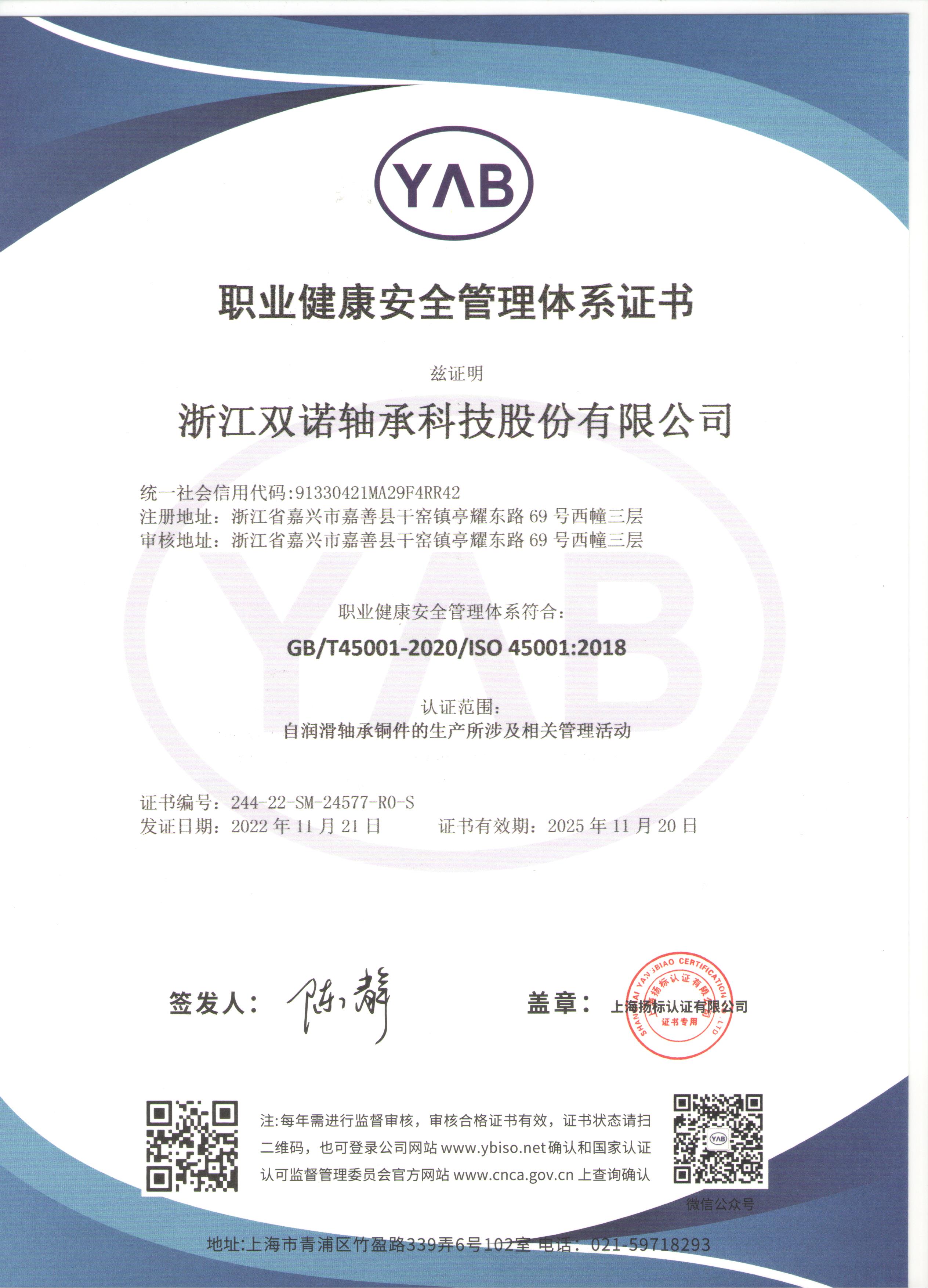
Zhejiang Shuangnuo Bearing Technology Co., Ltd. SÌ Cina JGBF Brass Oilless Ejector Flanged Guide Bearings Bushings fornitore E all ingrosso JGBF Brass Oilless Ejector Flanged Guide Bearings Bushings azienda, Siamo produttori professionali di vari prodotti in lega di rame autolubrificanti, utilizzando processi quali la fusione centrifuga, la fusione continua e la fusione in stampi metallici. I prodotti principali comprendono ottone, bronzo all alluminio, bronzo allo stagno, ecc., realizzati secondo gli standard nazionali. Su questa base elaboriamo e produciamo vari prodotti con cuscinetti autolubrificanti con intarsio massiccio. Produciamo anche prodotti bimetallici e molti altri tipi di prodotti utilizzando la tecnologia della sinterizzazione. Nei quasi dieci anni dalla sua fondazione, l azienda si è concentrata sulla ricerca, sullo sviluppo e sulla produzione di diversi nuovi cuscinetti autolubrificanti.

Durante il processo di produzione del prodotto, l azienda insiste sempre sulla fusione e sulla produzione indipendenti delle materie prime per garantire la qualità del prodotto fin dalla fonte; Il processo di fusione è monitorato in ogni sua fase e i prodotti finiti vengono testati tre volte tramite spettrometro prima, dentro e dopo il forno per confermare la composizione del materiale del prodotto. L azienda affida regolarmente a istituti di prova nazionali il compito di testare la composizione dei materiali e le proprietà meccaniche dei propri prodotti ed è in grado di fornire ai clienti che ne hanno bisogno relazioni di prova autorevoli. L azienda implementa una produzione integrata, dalla lavorazione dei materiali fino al prodotto finito, e dispone di oltre 80 macchinari principali, tra cui macchine utensili CNC avanzate, torni CNC e centri di lavorazione. L elevata capacità produttiva garantisce che la produzione dei materiali possa essere organizzata per i clienti nel più breve tempo possibile, riducendo così il ciclo produttivo.

  • 0+
    Stabilimento

    Shuangnuo è stata fondata nel 2014 e vanta 10 anni di esperienza nel settore.

  • 0+
    Attrezzature avanzate

    La nostra elevata capacità produttiva ci consente di organizzare la produzione dei materiali per i clienti il ​​più rapidamente possibile e di abbreviare il ciclo di produzione.

  • 0+
    Soddisfazione del cliente

    Abbiamo più di 5.000 clienti cooperativi in ​​tutto il mondo.

Le nostre notizie //
Notizie e approfondimenti.
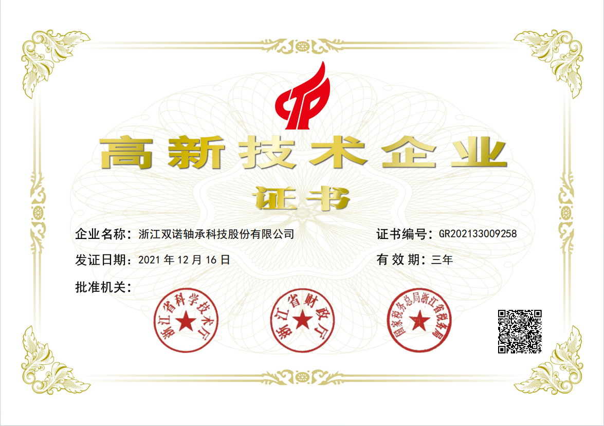
Il nostro onore //
onore.
Zhejiang Shuangnuo Bearing Technology Co., Ltd.
Rigoroso controllo di qualità //
Quando selezioni i prodotti, concentrati sulla qualità.
Concentrarsi su ogni processo per creare prodotti di alta qualità.
Siamo pienamente consapevoli che solo offrendo prodotti di alta qualità possiamo soddisfare le esigenze dei nostri clienti e consolidare una buona reputazione e credibilità.

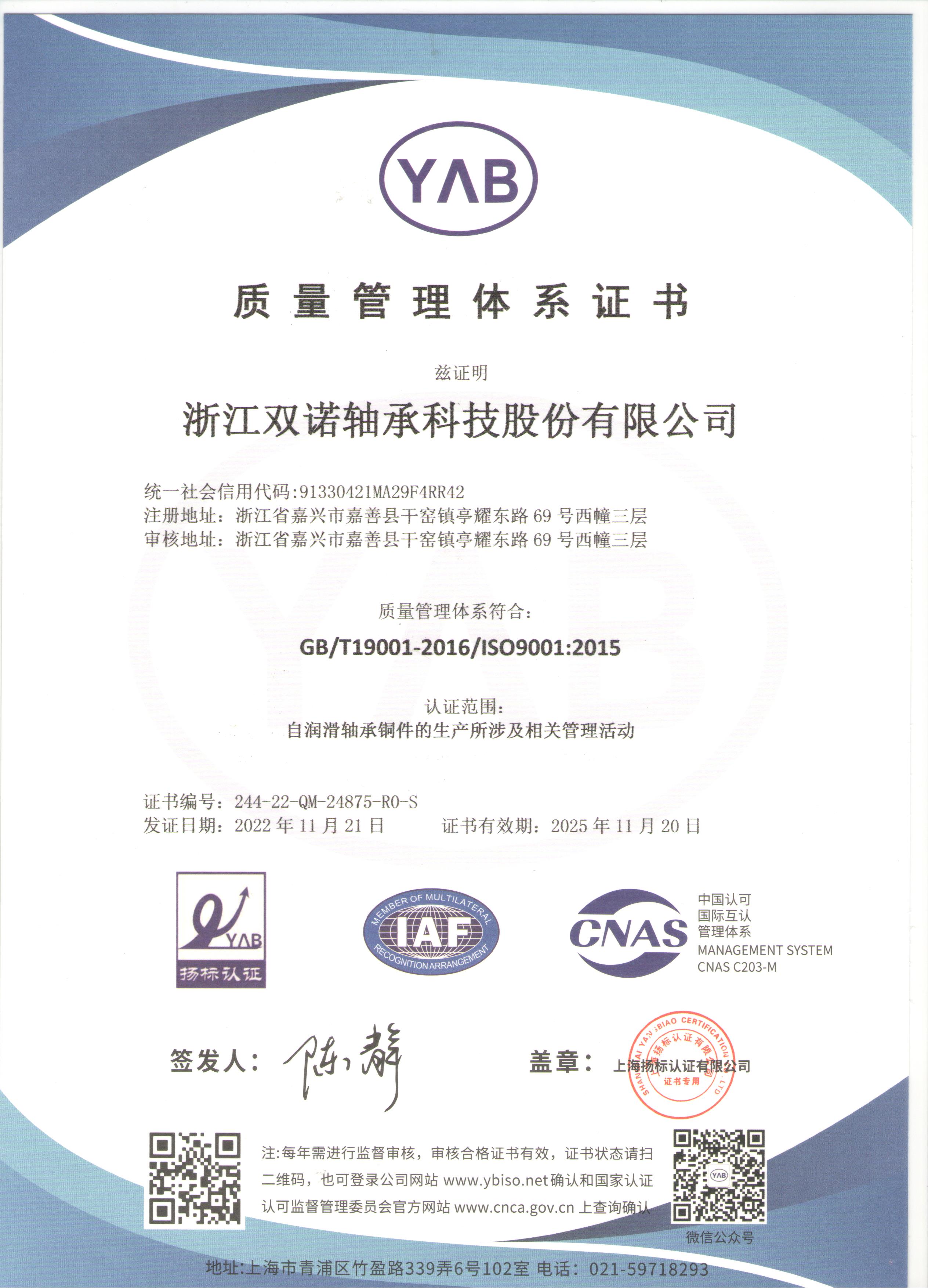
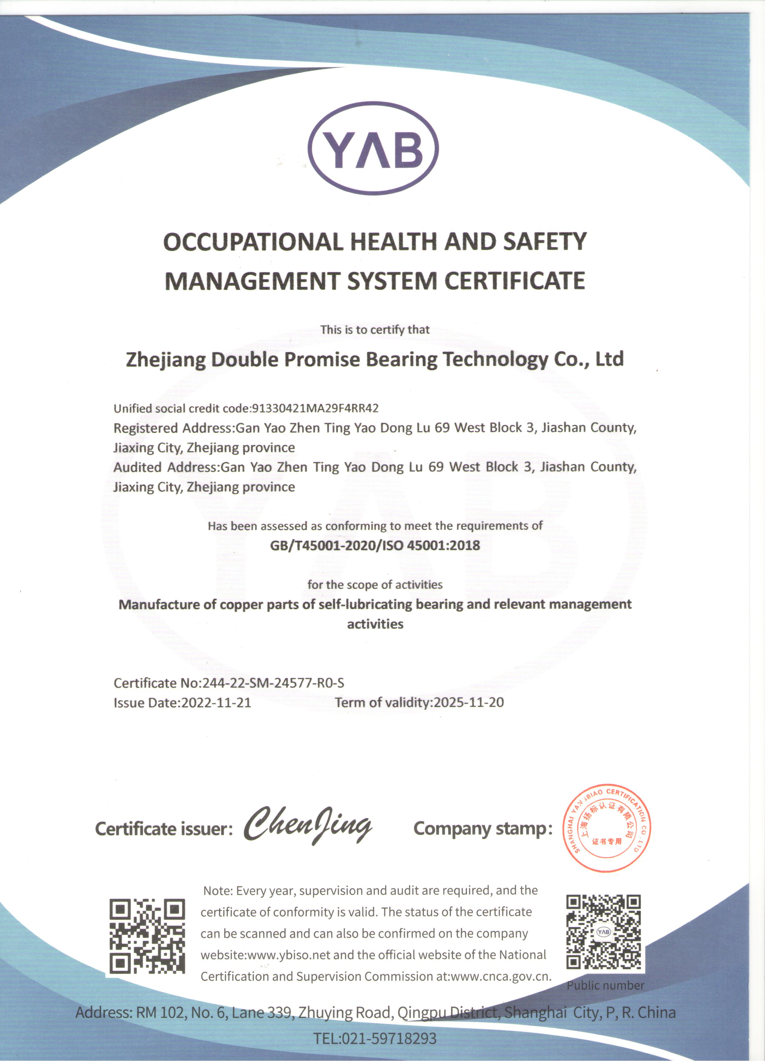
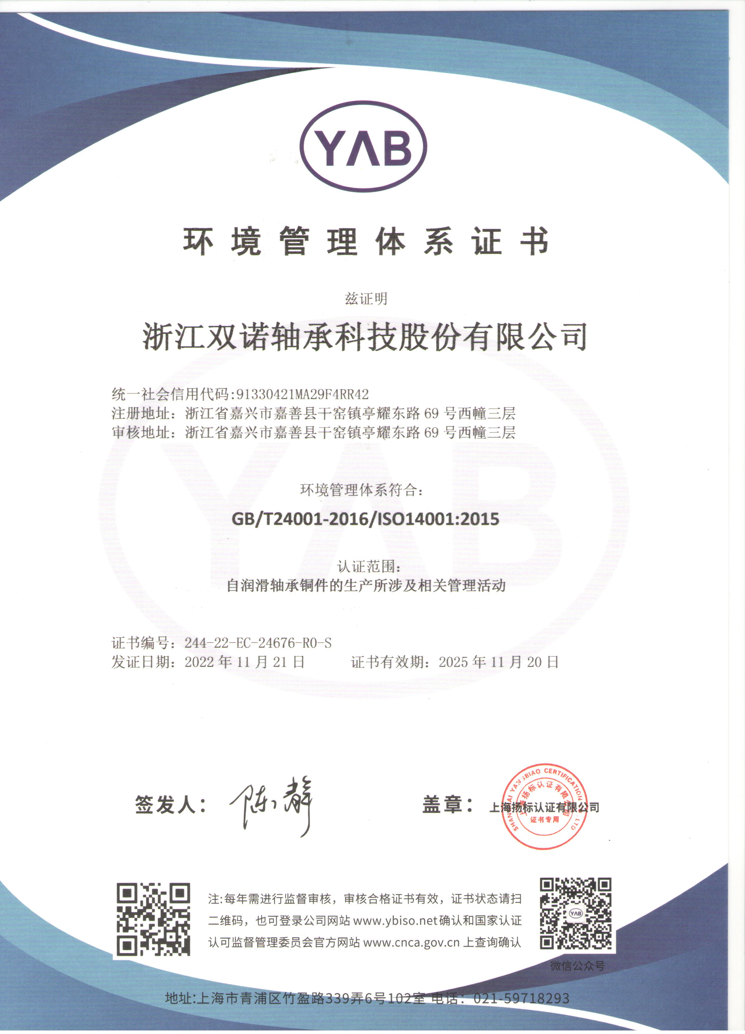
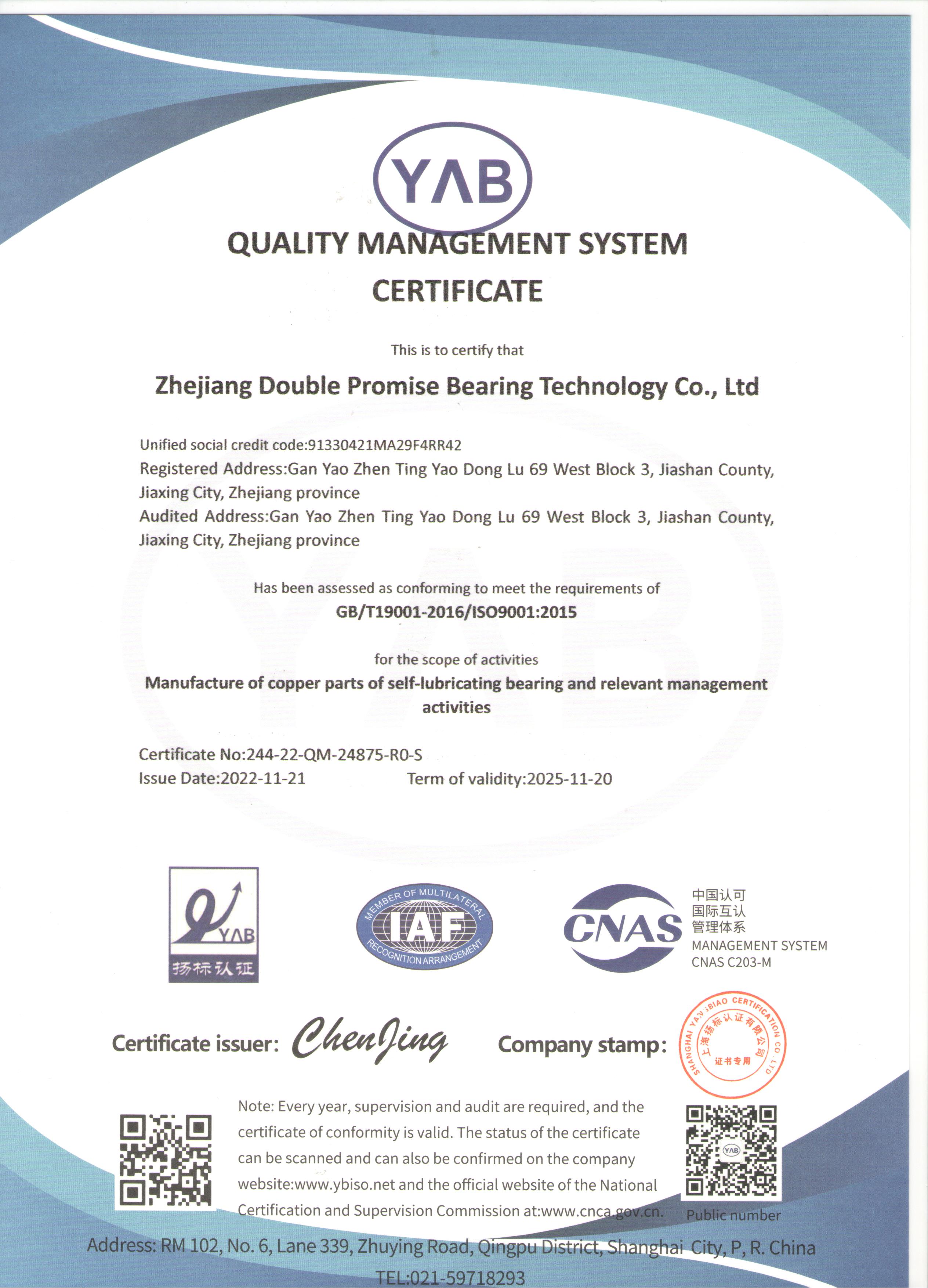
Richiediamo che i prodotti in lega di rame autolubrificanti siano conformi alle norme e ai regolamenti nazionali pertinenti. Rispetteremo rigorosamente gli standard nazionali di controllo qualità per garantire che ogni prodotto da noi fornito soddisfi i requisiti di qualità e venga sottoposto alle necessarie procedure di collaudo e certificazione.